(The glowing alternator light)
Looking through the owner’s manual for my 911, I noticed the description for the alternator warning light. You know this indicator as the little red light with the picture of a battery in it. The manual goes on to say that if this light flickers or stays on steady you should take the car in for repair. But what if it glows like Casper with a really bad sunburn? Believe it or not; but there is no reference to this Casper syndrome in the entire manual!
The first step in diagnosing a problem is in understanding how the system works. It is actually quite simple. A light bulb becomes illuminated when electricity (electrons) flows through the bulb. In order to have electron flow you need to have a difference in voltage potential on either side of the bulb. When you turn the key on there is battery voltage at one side of the alternator-warning light bulb from the ignition switch. If the alternator is not working there is no voltage at the other side of the bulb and the bulb lights up brightly. If the alternator is working and is producing charging voltage there will be 14 volts +/- .3 volts on each side of the bulb. With no difference in potential there will be no bulb illumination.
So what’s the deal when the light just glows dimly? The reason the light glows dimly is the there is only a slight difference in voltage potential. This occurs when for instance, there are 13 volts at one side of the bulb and only 10 volts at the other side of the bulb. The 3-volt difference creates the low voltage glow. But where did that missing 3 volts go? It got lost in a bad connection somewhere in the electrical system. Somewhere is the operative word and where a great deal of time can be lost in repairing this problem. Fortunately you do not need a big fancy (See expensive) piece of diagnostic equipment to locate the problem. All you need is a $12 Digital Multi Meter (DMM) from Radio Shack or Harbor Freight and a spool of small gauge wire (16-28guage) to extend the leads as necessary. Set the meter to DCV (Direct Current–Volts) and to the lowest range under 15 volts. This will most likely be the 0-20VDC or 0-40VDC scale on the test meter.
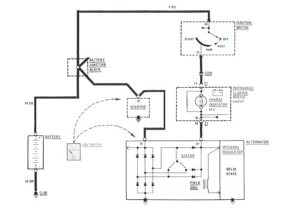
To test the wiring from the alternator to the battery you would hook one meter test lead to the B+ (battery positive) and one up to the alternator B+ connection. (This is a parallel voltage test) The B+ connection is marked #30 on all the electrical components in the diagram below. The electrons leaving the alternator that are being blocked at a bad connection (a burnt alternator to starter wire for instance) will see the voltage potential at each end of the circuit. The reading at the voltmeter indicates how much extra resistance is in this electrical circuit. Extra resistance will be indicated by a higher voltage reading when the meter is hooked up in parallel.
When dealing with electricity it is best to think of it as water. Let’s use a river as an example. When the river is flowing normally there is a slight loss of water from evaporation, etc. This is similar to the normal voltage drop in a properly running electrical system. Now let’s dam the river. The dam is similar to the resistance from corrosion or a bad connection. If we let a little bit of water flow through the dam, then the difference in how much water is being held back versus what is getting through is similar to the voltage drop experienced in a poorly operating system. Instead of having all that water behind the dam in “storage”, the energy is dissipated as heat at the point(s) of corrosion or at the bad connection. The measurement of that lost energy results in a voltage drop that we will see on our voltmeter.
To locate the bad connection is best to load the circuit while testing it. When testing the charging system circuit it is best to raise the RPM to 2500 and turn the headlights and blower fans on. This creates maximum alternator output and a high load condition with the accessories on. After a voltage loss is detected shorten the length of the test area to isolate the high resistance spot.
If you get a reading of 3 volts from the battery positive to the alternator B+ but the reading goes down to .5 volts when you move the test lead from the alternator to the starter you could conclude that the wire or connections from the alternator to the starter are bad. To verify this; connect the voltmeter from the B+ connection of the starter to the B+ connection of the alternator as shown in the diagram below. You should get a reading of 2.5 volts which will verify the high resistance problem area to the wire between the starter and alternator.
When making circuit tests like this it is said that .2 volts per connection is allowable. (But .1v is preferable)
With this formula let’s see how much voltage we could loose from the battery positive lead to the alternator:
Voltage at alternator B+ lead (14.2 volts)
0.2v – battery positive post to battery cable end.
0.2v – battery cable end to actual cable.
0.2v – battery cable to starter connection
0.2v – starter connection to alternator wire
0.2v – alternator wire to alternator connector.
1.0v – Total voltage loss
Voltage at the battery positive post should be 13.2 volts minimum voltage. Ideally we would like to see half of that amount for a total voltage drop of .5 volts or a battery voltage reading of 13.7 volts.
With this 13.2 volt reading at the battery we can see that this is the maximum allowable loss of voltage and anything greater than the .2v per connection would require repair.
Another telltale sign of a poor, high resistance connection is heat. While making the high load voltage test, run you fingers along the wiring and feel for isolated heat spots. If a spot in the wire is hot there may be broken strands or excessive corrosion inside causing high resistance.
But let’s not forget that electricity flows in a circle and that means we need to run these same tests on the negative side of the circuit. This would include the battery to chassis connection as well as any ground connections from the chassis to the power train or alternator.
These differ depending on model. 911/912/914’s have a ground strap at the transmission that gets forgotten and 924/944/968’s have a connection at the bell housing that gets ignored as well. 911’s also have a ground wire at the back of the alternator that is no treat to inspect.
This method of voltage checks applies to all electrical circuits as well. Starter, headlights, blower motors etc.
Good Luck.