It seems for some reason that failures come in groups and this month was no exception.
During the first quarter of this year I have been inundated with requests for information and repairs on ‘74-‘89 911 headlight hi/low switch failures.
These are commonly known as headlight dimmer switches or hi/low switches or turn signal dimmer switches.
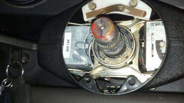
It is the combination switch on the left side of the steering column that operates the turn signal and headlight hi/low/flash feature.

The switch is the part marked 201.235 in this picture.
See anything else wrong in this picture? ( See my steering column bushing article )
This streak of failures started with 3 customers in 80’s 911’s and then got a little closer to home as my good friend Dan Chambers wanted me to drive his 911SC (The Black Pearl) for a few days and make sure everything was sorted out after a series of repairs had been completed. This particular evening I stayed at work a little later than usual and when it was time to leave I got in Dan’s car and headed for home. “Later” in this case would be without the benefit of natural sunlight. As I merged onto the freeway and courteously used my turn signal it got very bright in front of me from Dan’s H-4 headlights.
The high beam lights were stuck in the “on” position. This is not uncommon and a first stage of failure when the dimmer switch starts to go bad. So canceling the turn signal I optimistically expected it to return to low beam operation. No such luck for me this particular evening; and not wanting to be on the receiving end of some road rage I had to think quickly. So channeling my inner MacGyver I reached into the side pocket of my backpack sitting on the passenger seat next to me. I pulled out a Velcro computer cable tie that was already rolled up and slipped it between the stalk of the switch and the plastic housing. With just the right pressure the headlights returned to normal operation. No need to mention how I instinctively used my turn signal later in the drive and started this process all over again…

Dan Chamber’s 911SC “The Black Pearl” in safer daylight hours.
Now for a little history on this switch. Power comes from the battery to the ignition switch to the headlight pull switch to the hi/low switch to the fuse box to the headlights. There are no relays so this is full headlight electrical current. High current means high heat. Think about the wires in your toaster in the morning. That is a lot of wiring and connectors and switch contacts to get hot. When these switches were designed, headlights were not very bright and didn’t impose the current load that they do with today’s high power halogen and increased wattage bulbs.
So today we are putting even more power through a poorly designed switch. The second problem is the “They just don’t make things like they used to” factor. This is true in this case for sure as an original switch may last 30-years and a replacement switch may only last 10. The materials are just not as good and the switches are more easily damaged by the heat of the high current headlights.
Case in point: Of the 5 headlight dimmer switches I have replaced over a 60 day period, all replaced an original switch. All second switches failed in a 2-8 year period. Two were factory Porsche switches, two were non-factory high quality and one was of questionable on-line quality.
Below we can see the switch in question. Notice the contacts that look like match sticks. This is where all of the current travels, making heat and bending and distorting the contacts out of position. This heat also melts and/or distorts the plastic in the switch and changes the shape of the main pivot bar in the switch. All of these causing the unintended activation of the high beams.

Note small contact fingers and the bend in the actuation bar.
So instead of replacing these switches every 10 years there is a simple solution short of only driving in the daylight hours. Newer cars all have headlight relays, and the switches and controls only signal the relay to switch the power. That means about a 98% reduction in power and heat at the hi/low switch. As an added bonus the power comes from the battery to the relay to the fuse box and then finally to the headlights. This removes the ignition switch, headlight pull switch and hi/low switch from the equation completely and provides even higher voltage to the headlights. More voltage means brighter headlights for eyes that may not see as well as they once did
You could go to your local electronics store and scrounge up replays and holders and special connectors but there is an easier way. There is a company that sells a complete kit for ‘74-‘89 911’s. This company is J-West Engineering www.jwesteng.com and they are known for their high end shift systems for pre-1990 Porsches, but have some nice electrical parts as well. They sell two headlight kits, a universal and 911 specific kit. The 911 kit requires a few connectors be changed, but has a required relay bracket that attaches to the fuse panel mounting screw perfectly; so that is the one you will want to use.

J-West relay kit and instruction booklet
The kit comes with reasonable instructions but I will give you a more detailed list.
- Disconnect the battery ground cable.
- Remove the fuse panel cover.
- Now take out your cell phone or digital camera and take a few shots of the fuse panel in case you get distracted and forget what color wire or relay went where. Does the carpet snap bracket face forward or back?? Was that black, black, red on the relays or black, red, black?? Not to mention the aftermarket stereo wiring you had to move…
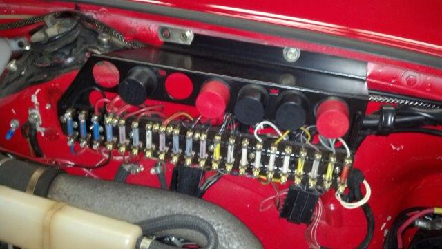
Fuse panel relays in place.
- Now remove the first three relays (counting from the front of the car)
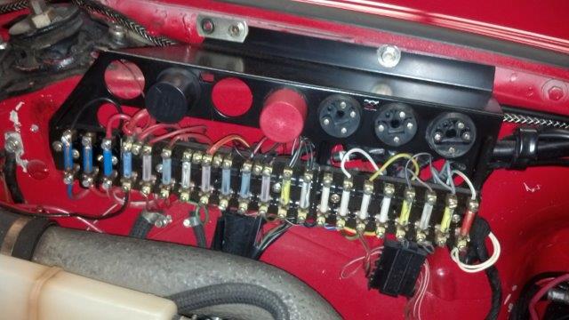
Fuse panel relays removed
- Remove the mounting screws from the top of the fuse box with a 10mm socket.
- Remove the Phillips head screws mounting the fuse box to the body at the bottom.
Don’t lose the white plastic spacer under this screw!
- Be very careful not to lose the white plastic spacer on the rear lower Phillips head screw.
- Open up the metal wire band in front of the fuse box holding the main harness.

Releasing the harness tie allows the fuse panel to move easily.
- Now gently pull the fuse box away from the fender to access the wiring.
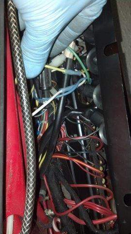
Pulled away there is now room to deal with new wiring.
- Counting from the front of the car find fuses 6 and 7. Disconnect the wires from the top of the fuse holder.
- Cut off the metal sleeve and strip about ¼ inch of insulation off the wire (#6 yellow, #7 white).
- Take your relay kit and prepare the connections.
- The main red wire needs a 6mm ring connector installed and attaches to the 6mm power stud on the battery.
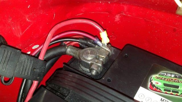
Battery B+ relay power connection.
- The black wire is the relay ground and gets an 8mm ring connector and is attached to the battery man ground stud near the washer pump for earlier cars.

Ground stud just forward of the battery.
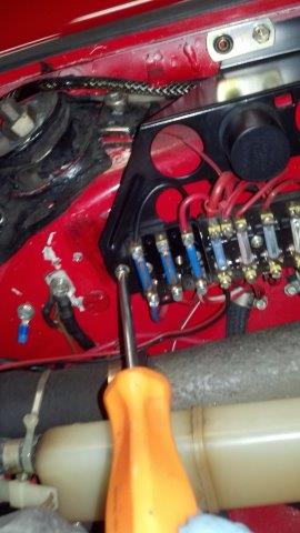
- Later cars can use the more convenient 6mm ground point just rearward of the fuse box. Install a 6mm ring connector for these cars.

Tip of Screwdriver shows later ground point.
- Now we need to feed the relay wires behind the fuse box. Tape the yellow, white, blue and green wires together and feed them behind the fuse box.
- Once behind the fuse box, unwrap the relay wires and attach the green wire to fuse #6 and the blue wire to fuse #7. You can just attach the wires or solder the ends for a better connection path.

New blue and green wires powering fuse box and yellow and white signaling the relay.
- Now attach the yellow relay wire to the yellow wire that you took off the fuse holder.
- Then attach the white relay wire to the white wire that you took off the fuse holder.
- You can just use the butt connectors that come in the kit or you can solder the wire and use heat shrink tubing for insulation.
- Now neatly tuck the wires behind the fuse panel and reattach it except for the forward lower screw.
- Attach the double relay kit to the car using the lower forward screw mounting point.
- 1985 and later cars have a flat 7-pin electrical plug with red/white wires at this forward lower screw. If you have one of these cars you will need to use a longer screw and plastic spacer like is used on the other end of the fuse panel. These don’t have to be ordered from Porsche, substitutes can be had at Home Depot. Specifically you will want a 1/2in x 1/2in x .194 nylon spacer (SKU # 595383) and #8 x 1-1/4 sheet metal screws (SKU # 114349). The plastic spacers come in a two pack as if they know you were going to drop the rear one under the black hole that lives under the fuel filler neck.

Relay with spacer and longer screw.

Assembled headlight relays and wiring with round relays back in place.
- Now plug the relays back in and attach the battery ground cable.
- Time to test the headlights. Do the high beams come on when you pull the lever back or is that the low beams?
- If they work backwards just reverse the #6 and #7 fuse wire locations.
- I am sure everything works perfectly so you can now put the fuse panel cover and trunk carpet back into position.
You now have corrected to problem of overheating the switch but unless that switch was new it has still suffered damage. If in the future your headlights start to flash there still may be hope to save the switch.
The linkage in the switch can still be adjusted if the plastic and contact fingers are now damaged.
- Remove horn relay in fuse panel (Trust me)
- Mark location and remove the steering wheel.
Switches exposed with steering wheel removed.
Now remove upper and lower black covers:

Combination switches with covers removed.
- Remove two screws holding the white horn contact.
- Remove two small black screws on sides of the covers along seam line.
- Remove two screws below the horn contact and two corresponding screws in the lower cover.
- Now carefully pull the covers off and set aside.
- Now look at the switch from the side and note the movement of the actuation bar as you operate the high beams. The top of the bar will likely need to be bent forward.
Note small contact fingers and the bend in the actuation bar.
(STOP) – This next step is a delicate operation and can break the switch if done incorrectly.
- If you are adventurous, take two pairs of duck bill pliers (or stubby needle nose pliers) and grab the top and bottom of the bar and give it a gentle bend. You can find a cheap precision plier set at Harbor Freight item 60826 for under $10. Multiple small adjustments are better than one over adjustment. Be careful.
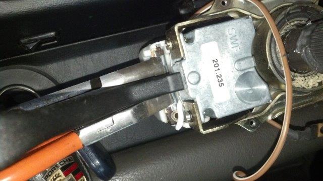
Twisting the bent contact bar to restore tension to the contact fingers.
Perfect adjustment and ready to reassemble?
Just assemble in reverse order and be sure to route the upper horn contact wire and lower ground wire properly.
Don’t forget to return the horn relay into position and test the horn.
Good Luck